About our recent service interruption: We appreciate your patience during the downtime and will be continuing to monitor our servers to avoid similar interruptions in service. We apologize for any inconvenience this may have caused and we appreciate your understanding. We encourage users editing the Wiki to retain records of their edits in the event of another unexpected interruption.×
baprc wrote:Hey guys, how far from the testing wall will the base actually be? I understand that this new J-hook allows for a greater height (16.4 cm I believe is what was mentioned). I know that the straight part of the J-hook is 2.5 cm long but the actual base won't rest there, rather at the bottom "corner" of the J-hook. So, how far is that part (if that is where the base rests) from the wall?
The first rule is read and understand the rules......
There you will see that the 2.5cm you note is not the length of the straight part of the j-hook, it is the distance from the wall to the 'closest edge of the hook.' Look at the photo in the rules. As suggested just a few posts back, get a hook that meets the specs, or google up the specs; lay it out, figure out the geometry/dimensions
The simplest way that I have seen is to make a jig as described a few pages back. I made the L Jig, positioned hook complying with the rules, 20 cm above contact depth line, etc, and a straight board attached 90 degrees, where the contact line is, making an L shape. The board at the bottom is about two centimeters less than the 40-45 cm length limit. This way I have room to work with the distal end when I place the compression member. After placing the compression member on to the jig, it hangs off a few centimeter, allowing space to attach tension, glue, etc. I already had the tension members attached to the base, so the only step left is to finish distal end. I center the base onto the J hook, and fix the angle. When I put the tension next to the compression at the intersection where they will glue, I tugged the two tension cords slightly. This positioned the base, and put the base into its natural position so that when you are testing, it will be at the best spot and cause the least unneeded or unnecessary stress caused by putting the base at the wrong angle or wrong place. This is simulating the direction of the forces that will be playing when testing the boomilever.
This solves the whole issue of base positioning. Since I didn't now the exact length needed for the base, I simply left a few extra inches. After gluing was done, all that is needed is to snip and file the extra length left behind off.
(By the way, hopefully I should be able to post up the results of my first boom in a few day, once I test it, iA)
Noor-ul-Iman School
2012 Events:
Forestry
Storm The Castle
2013 Events:
Boomilever
Shock Value
Forestry
I know the voices aren't real, but they have some great ideas..
We used the same method as UQonyx to connect T members with base & C members. It was a challenge to have T members on both side connected the same (angle & straightness). We added a small triangular piece to fill the gap between T & C members and we sanded the base sides to create an angle. After we glued, one T member was straight, the other was bent a little even though we tried as hard as we could to keep both sides of the base & the gap filling pieces as identical as we could.
Just tested another boomilever. We used the same dimension of box beam but increased the wood density by 1.35 and it still broke at the middle of C member (we can see the middle of the C members bent up this time). The efficency increased by 27.45%. We'll increase the high dimension of C members on our next boomilever as Iwonder recommended.
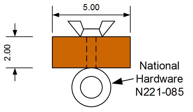
What you show does meet the rules.
That said, the rules do not include the spec number.
Also (see discussion earlier), while the length of eyebolt you show is ok under the rules, the rules simply say no longer than 4 inches; the rules do not require it to be as short as you've shown.
Of course. I hadn't considered this case last year, even though the rules had no eyebolt length specification but now I'm concerned about the possibility that this configuration could be required at Nationals and if so, we should allow for it locally. Just wondering if anyone else is planning for this contingency.
Of course. I hadn't considered this case last year, even though the rules had no eyebolt length specification but now I'm concerned about the possibility that this configuration could be required at Nationals and if so, we should allow for it locally. Just wondering if anyone else is planning for this contingency.
-Scot
My concern, exactly, Scott; why I earlier raised the issue, and highlighted that whether intentional or not, the lack of a specified minimum length would allow ESs to eliminate single compression member designs. I believe strongly, as I did when I raised it, this needs an official clarification.
Len
I am really confused about this whole new mounting system with the J=hooks. I have read the past posts but I still don't understand how the mounting system is supposed to look like. Can someone please draw of explain thoroughly about this matter? Thanks
aznman908 wrote:I am really confused about this whole new mounting system with the J=hooks. I have read the past posts but I still don't understand how the mounting system is supposed to look like. Can someone please draw of explain thoroughly about this matter? Thanks
Think of something that would "hook" onto a hook and still attach to your tension or compression members... How might you connect two water buffalos together?