
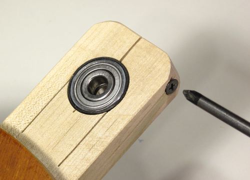
“Based on your description, I'm envisioning something like this: http://woodgears.ca/gear/bearing_mount2.jpg , where the wood piece is as thick as the bearing (the outside faces of the bearing are flush with the outside faces of the wood).
Now with a design like that, how do you prevent the bearing from slipping out of the holder? The image I've linked to above shows a a screw used to tighten the wood and grasp the bearing. Any other options? A couple self-threading set screws coming in from the top and bottom of the wooden holder might be able to be used.”
What we’re using is sort of like that. We’re using flanged bearings- there is a little lip around one edge of the outer bearing race- its on the order of 1/64th” thick, w/ a radius about 1/64th bigger than the race. So when the bearing goes into a ¼” hole- a ¼” square hole- the flange catches the edges, and stops the bearing from going on through the hole. Then on two sides, we run little retaining strips- out of 1/16th” thick lexan, ¼” x ½”. Along one edge, there’s a little cut-out. The cross section of that cut-out is a little bigger than 1/64th x 1/64th”, like a few thousandths bigger. So, when you glue two of these strips onto the bearing carrier plate, with the cut-out edge against the bearing, they overlap the flange, so the bearing can’t come back out of the hole. Looking down the axle, the flange now locks the bearing from moving in/away from you (because its catching the edges of the ¼ x ¼ hole), and it locks the bearing from moving out/toward you, because its catching the retaining strips.
Now, here’s the key difference in this setup, and the one shown in your link. The advantages of what I’m about to describe are small (unless your axle is seriously not straight and/or the planes of your bearings are way off being parallel and vertical to the axle)- this alone won’t make ‘the winning difference.’ But if you put enough little, advantageous differences together, they can add up to a measurable, positive difference. For a live axle, in the perfect case, your axle is perfectly straight, and the bearings are perfectly parallel, and perpendicular to the axle; the friction is that designed into/inherent in the bearings. However, if the bearing planes are not parallel, and/or if the axle is not perfectly straight, and if the bearing alignments are.....locked down- anchored in a way that the bearing can’t move – like in the setup you’re showing- then you get some amount of binding, and flexing of the axle; friction is higher, the vehicle slows down faster than it would with ‘ideal” alignment. You can see this effect if you set up a little test jig- a piece of board as wide as the distance between your bearings. On that, glue on a couple of strips that are the width of your bearings. Mount them on the top of the board, at and along the edges, so they are parallel. So, if you take your axle, with the wheels attached, and put it across these strips, the bearings will ride on top of the strips. On top of those strips, on one side of the axle, on each side, glue a little block butting up against the bearing. Then across the axle from each bearing, glue down another holder block. When you glue these second blocks on, slip a piece of paper in between the bearing and the block. Position the block so that with the paper shim in place, its nice and snug against the bearing. Pull the paper out, and you’ll have 2-3 thousandths of an inch free-play. Now spin the axle up. Looking down on the bearings, unless you’re incredibly lucky and you’re axle is perfectly straight, you will see the bearings wobble.
So, you want the bearing locations “fixed’- where the bearing can’t move fore and aft, so you don’t get....”steering wander”, but you also want the (plane of) the bearing to be able to wobble around the axis of the axle. Here’s how we got both.
Bearing o.d. is ¼”, bearing width is 1/18th”, bearing holder plates are 1/8th thickness, flanges on one side of the bearings. Bearing holder holes are ¼” square (mark, cut/grind to close, then carefully work with a little file-file; check, fit, file some more, check fit, etc., etc.-till you get a nice snug fit. The inside edges of the bearing hole will be flat, and will fit flat against the flat outside of the bearing’s outer race; the bearing will essentially not be able to wobble. Now, from the side of the bearing holder plate away from the flange, using your little, file you want to taper the hole; file away the edge that’s away from the flange. Angle doesn’t matter much, say 20 degrees. As you file more, the edge of your cut will move toward the flange side. File till on the flange side you still have a little un-filed material, say 1/32nd to 1/64th. Be careful not to file/cut into the edge of the hole on the flange side. When you’ve done all 3 sides, on your flange side, your hole, the hole will still be the exact ¼ x ¼ you started with; on the other side, it will be more like 5/16ths x 5/16ths. Because you left the flange side of the hole alone, the bearing will still fit snugly. But, now, because the bearing is only riding on the thin edge, it can wobble.
Two things to finish up. The flange retainer strips I mentioned earlier have to have enough clearance in the cut-out that overlaps the flanges (some more careful file work), so that when the bearing wobbles there is room- thee flange is not pinned against the bearing holder plate. The thickness of a piece of paper- 2-3 thousandths is plenty. Put the bearing on a nice hard surface, laying on one face; put a little piece of paper on top (piece of a sticky-note works nicely). Push your bearing retainer strip, with the lip overlapping the flange, down- with file, adjust the depth to your lip so that when the lip is in contact with the flange, the face of the block is solidly in contact with the plate the bearing is sitting on. Last bit is to do your top retainer strip. It’s also out of 1/8th thick lexan, like ¼” x ¾”. In the middle one edge of it, about ¼” wide, taper the edge like you’ve done to the other 3 sides of the bearing hole. That way, when you glue it across the top of your bearing holder hole, you have a 4-sided, ¼ x ¼ hole; bearing can’t move fore and aft, or up and down, but it can wobble......
And,
“On a different topic, what types of metals are you using for the axles? I've been using Zinc threaded rods that I've found at HomeDepot. They also have stainless steel, but it's about 5 times more expensive.”
On the front – a live axle- with both wheels attached to the axle- we use 1/8th titanium; weight and stiffness.
On the rear – a dead axle- bearings in the wheels – we use 1/8th” carbon fiber.
Hope this helps.
Under the rules, that's not allowed- no stored energy that contributes to the energy of the vehicle- only what you get by rolling down the ramp...See rule 3.c.Cheese_Muffin_Man wrote:Does anyone have any ideas on an elastic method to help propel our vehicles?
